Sunday, March 13, 2016


MAIN PROJECT INTRODUCTION: INTRUSION DETECTOR

For my main project, I have decided to turn my raspberry pi into a motion sensing device, capable of detecting the motion of a door (or anything else). When this project is complete, it should be attached to a door as a security feature and anytime someone opens or moves that door the pi will sound an alarm and send an sms (text message) notification.

MATERIALS

- Raspberry Pi with OS installed
- ADXL345 Accelerometer
- Wifi dongle
- A breadboard/T-cobbler with male to male jumper cables OR female jumper cables only
- A power bank
- Speaker with 3.5mm connection
- Any case to house the hardware
- Velcro/wall hooks

I am referencing the following tutorial as a guide for my project:
https://www.hackster.io/vijayenthiran/intelligent-door-e59113?ref=part&ref_id=6488&offset=13

INSTALLATION OF ACCELEROMETER

1. If using a breadboard pick a side to attach the accelerometer
2. Using jumper cables (male to male) from accelerometer to breadboard:
    - 3V3 of accelerometer to 3V3 of breadboard
    - Ground of accelerometer to ground of breadboard
    - SCL to SCL
    - SDA to SDA


Accelerometer pin connections:
 - VCC_IN
 - 3.3V
 - GND
 - SCL
 - SDA


Connected accelerometer:


3. Install the accelerometer tools and turn on i2c in the configuration menu of the pi:


A previous image shows the accelerometer wired directly through the breadboard. In my original set up, the sensor was connected to the breadboard with a connected series of pins with the wires then connecting to adjacent spots on the board. For a long time I was having trouble getting the pi to detect my sensor. I was not sure if the sensor was bad or if I was doing something wrong. There seemed to be nobody on the internet who was having the same issue. Suddenly the light came on the sensor as I was attempting to remove it from the breadboard and at that point I realized the pins that came with the sensor were not long enough to connect to the breadboard so I rewired to the above image.

4. Install the adxl345 library to output orientation readings from the rpi:


Example readings from the connected accelerometer:


AWS IOT FOR SMS NOTIFICATIONS 

AWS IoT stands for Amazon Web Service Internet of Things. 
  
1. Create an Amazon Web Service account and access AWS IoT from the menu:


2. Create a resource named "raspberry_pi":


3. Generate certificate and policy keys in order to connect to the pi:


4. Install Node.js to the pi inside of aws-iot directory:


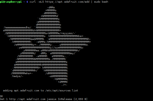
5. Install the device sdk:


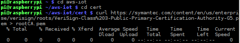
6. Create folder for certification keys inside of aws-iot folder and install Symantec certification file:


7. On the AWS connect the raspberry pi to the service


8. Set up a topic to subscribe to on the AWS which will listen to the RPi for door movement


Messages received to the web service:


RECEIVING SMS MESSAGES THROUGH AWS IOT

1. On the AWS use the SNS link to create a topic


2. Name the topic


3. Add phone number or email address to the service


4. Link phone number or email address to the web service in order to forward messages


SMS alerts:


ALARM FUNCTIONALITY

1. Plug speaker into usb power source and 3.5mm jack of the Pi

*Command to force RPi to output audio through the 3.5mm headphone jack instead of HDMI:


2. Select an alarm mp3 file and save it in the aws-iot folder


3. Code for alarm integration (add to main intrusion detection code file if statement)


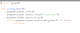
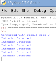
Code for intrusion detection with alarm:


COMPLETED PROJECT


Saturday, March 12, 2016

OPERATING THE PI FROM MY LAPTOP

Moving the pi has been very cumbersome because until now I have been using a small TV as my monitor at home with a separate usb keyboard. At, school I use one of the school keyboards and monitor. Connecting and disconnecting the cords has been somewhat of a hassle so I decided to connect my laptop to the raspberry pi on a VNC network. This allows me to display the raspberry pi screen on my laptop with full access to files and features. I read many internet sites and tutorials to accomplish this. It was a fairly straight forward process, and although many small details did cause various problems, I was eventually able to figure it out. I now have a much more compact an movable raspberry pi hardware setup.

The most helpful guide I found to help me with setting up wireless screen sharing on my laptop is here:
https://www.raspberrypi.org/documentation/remote-access/vnc/

and then here(for a mac computer): https://www.raspberrypi.org/documentation/remote-access/vnc/mac.md

In short, steps to set up a VNC network with a monitor, keyboard, and mouse:
1. Connect Raspberry pi to monitor
2. Install tight vnc to the raspberry pi
3. Locate and remember the IP address of your pi
4. Start a vnc session on the pi
5. Install a VNC viewer or screen sharing app on your mac or pc
6. Connect to the VNC server with your computer using the IP address of the pi.

I used the secure shell (SSH) to access the raspberry pi's terminal from the terminal on my mac, however this can all be done directly through the pi with a monitor, mouse, and keyboard attatched.

Steps to set up a VNC network without a monitor:
1. Connect Rpi to laptop through ethernet and usb power
2. Enable internet sharing on your laptop
3. Use the app called Pi Finder to locate the IP address of the raspberry pi
4. SSH into pi console with ssh pi@192.168.x.x(IP address)
Continue with steps 4 an beyond above.

Friday, February 19, 2016

TWITTER MENTION CATCHER

I had originally started off with a Morse code translator for my LED project. However, after some thought I decided to change my project to listen for twitter mentions and blink the LED accordingly. The raspberry pi monitors my Twitter account, and if anyone sends a tweet containing my Twitter username, the pi will blink the LED as well as display the message in the python shell.

The following link was my guide and starting point for this project:

https://learn.sparkfun.com/tutorials/raspberry-pi-twitter-monitor

When coding this project, I ran into a few problems. I was getting errors from python because I did not update and install the twitter packages to python correctly. It had appeared that everything was installed correctly at first but after doing some research I realized that Python 3, which I was coding in, required separate commands to install the packages. The other problem I ran into had to do with a print statement. It was a very simple solution when I finally figured out that Python 3 used parentheses after the print command while they are not present in python 2.

Below is my final updated code:

Sunday, February 14, 2016

PYTHON CODE ISSUES

https://www.cl.cam.ac.uk/projects/raspberrypi/tutorials/robot/morse_code/

Using the above link a a guide I was able to write a python program that uses all 6 of my LEDs from the light show in order to translate Morse code as flashes. The only problem I ran into was figuring out how to code the program to take user input for the translation. As of now the program will only translate a pre-defined string.

This is a video of my name "Tyler" in morse code:


 LED LIGHT SHOW

I have begun documenting my project using Fritzing. I created the breadboard schematic using the software and also wrote a description of how to assemble this project as well as a description of its workings. Once I set up my raspberry pi and connected the accessories, I began experimenting with the code for the light show. I wanted to create a light show that was a bit more complicated than the very first one I created, while still using the same 6 LEDs.

This is a video of the second light show I created:


This is a portion of my source code:


Sunday, February 7, 2016

LED LIGHT SHOW

In my LED project, I was required to set up an LED light show using the raspberry pi and python coding. I used the following chart as a reference when wiring my LEDs:


I started with one LED on a breadboard connected to the pi and tested several on/off commands in the console. Afterwards I added more LEDs and lit them according to the instructions given to me. At first I had a little bit of trouble figuring out how to code four LEDs to blink simultaneously, however, I eventually figured out that the solution to the problem was much more simple than I originally thought. Once I figured this out I was able to use what I learned in order to create my light show using six LEDs.

This project consists of:
- 6 LED lights
- 6 220 ohm resistors
- jumper cables
- breadboard (w/ T-cobbler)
- raspberry pi

Steps to build:
1. Use jumper cable or T-cobbler to connect the GPIO pins of the raspberry pi to the breadboard
2. Insert 6 LED's in a row on the breadboard, with the short leg going to ground and the long leg to a resistor
3. Wire the other ends of the resistors to GPIO 18, 23, 24, 25, 19, and 22.


This is a video of a very basic light show:


These are pictures of my LED/breadboard setup:


Monday, February 1, 2016

BEGINNING

I received my raspberry pi after ordering it from amazon.com where it took a little less than a week to arrive, and I was able to connect all of the accessories as well as power on and update the pi. I experimented with console commands learned in class and also explored the various menus and settings of the raspberry pi. After setting up the pi, I brought it to class where we experimented with turning on an off an LED light using console commands. My next step will be to create a simple sequence of LED lights that turn on and off using a circuit.